


1. Introduction
An S-R latch (Set-Reset Latch) is a fundamental digital circuit widely used for storing and holding state information. It is a bistable circuit composed of basic logic gates such as AND, OR, and inverters. As the foundation for flip-flops, the S-R latch is commonly applied in digital systems for state storage, signal control, and other applications. This article will explore the working principle, truth table, symbol representation, and applications of the S-R latch.
2. Basic Structure of the S-R Latch
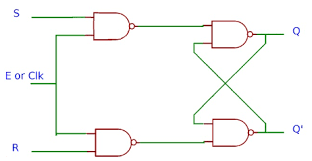
The S-R latch typically has two input terminals: Set (S) and Reset (R), as well as two output terminals: Q and Q‾\overline{Q}. Here, Q represents the latch’s output state, while Q‾\overline{Q} is the inverse output of Q. The core logic of the S-R latch is to control its state through the Set and Reset input signals.
The circuit of the S-R latch can be implemented using AND gates and inverters, and a common implementation is based on cross-coupled AND gates and inverters. The Set and Reset inputs are fed to the inputs of two AND gates, whose outputs are connected to the inputs of inverters. The outputs of the inverters are then connected to the next stage of the circuit.
3. Working Principle of the S-R Latch
The operation of the S-R latch depends on the combination of input signals S and R. The output Q and Q‾\overline{Q} will change according to the input signal combination and maintain a certain state. The working principle is as follows:
- Set State (S = 1, R = 0): When the Set input (S) is 1 and Reset input (R) is 0, the latch enters the set state. In this case, Q will be 1, and Q‾\overline{Q} will be 0.
- Reset State (S = 0, R = 1): When S = 0 and R = 1, the latch enters the reset state. In this case, Q will be 0, and Q‾\overline{Q} will be 1.
- Hold State (S = 0, R = 0): When both S and R are 0, the latch will maintain its current state, keeping the previous values of Q and Q‾\overline{Q}.
- Forbidden State (S = 1, R = 1): When both S and R are 1, this is an invalid or forbidden state. In this case, Q and Q‾\overline{Q} will both be 0, leading to an inconsistent output. This state should be avoided in practical applications.
4. Truth Table of the S-R Latch
| S | R | Q (Next State) | Q‾\overline{Q} (Next State) |
|---|---|---|---|
| 0 | 0 | Hold (Q remains) | Hold (Q‾\overline{Q} remains) |
| 0 | 1 | 0 | 1 |
| 1 | 0 | 1 | 0 |
| 1 | 1 | Forbidden (Undefined) | Forbidden (Undefined) |
- S = 0, R = 0: The latch maintains its current state, with Q and Q‾\overline{Q} unchanged.
- S = 0, R = 1: The latch is reset, with Q = 0 and Q‾\overline{Q} = 1.
- S = 1, R = 0: The latch is set, with Q = 1 and Q‾\overline{Q} = 0.
- S = 1, R = 1: This is an illegal state where both Q and Q‾\overline{Q} would be 0, causing an inconsistent output.
5.Applications of the S-R Latch
Due to its simple structure and reliable storage functionality, the S-R latch has a wide range of applications in digital circuits. It is commonly used in the following areas:
- Data Storage: The S-R latch can store one bit of binary information, making it useful as a simple storage unit or data buffer.
- Control Signal Holding: In digital control systems, the S-R latch is used to hold control signals, maintaining their state until reset.
- State Machines: In finite state machine (FSM) design, the S-R latch is used to store and transition between states, helping the circuit maintain its current state.
6. Conclusion
The S-R latch is a fundamental storage element with a simple yet important functionality. By controlling the Set and Reset inputs, the S-R latch can hold or change its output state. Although it forms the basis for flip-flops, more complex and reliable flip-flops (such as D flip-flops or J-K flip-flops) are typically used in modern digital circuits, especially in applications that require multiple inputs or higher frequency. Nevertheless, the S-R latch remains an essential starting point for learning about digital and sequential circuit design.