


An attenuator is a device or component used to reduce the strength or energy of a signal. It is commonly found in electronics and communications, and is used to adjust signal levels in circuits or to match signal levels between devices. The function of an attenuator is to reduce the amplitude of an input signal without changing its waveform or frequency characteristics.
Types and structures of attenuators:
Attenuators can adopt a variety of different structures and working principles, including:
Fixed attenuator: Fixed at a preset attenuation value, commonly expressed in decibels (dB).
Variable attenuator: Its attenuation value can be adjusted by mechanical or electronic means to dynamically adjust the signal strength during operation.
Reflective attenuator: Reflects part of the signal back to the source or absorbs it instead of passing it completely.

Main features and functions:
Signal control: Attenuators are able to precisely control the strength of the input signal. In lab and test environments, they are often used to ensure that equipment is operating at safe signal levels to avoid overload or damage.
Matching impedance: Attenuators can be used to adjust the impedance matching between different circuits or equipment to ensure the efficiency and quality of signal transmission.
Test and measurement: In measurement and calibration equipment, attenuators are used to create known signal levels for accurate testing and measurement.
Noise control: In communication systems, attenuators help control and reduce the noise level in the system to improve the clarity and stability of the signal.
Attenuator circuits:
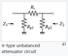
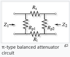
The basic circuits used in attenuators are the π-type attenuator and the T-type attenuator. Depending on whether the line geometry to be used is balanced or unbalanced, they may need to be balanced or unbalanced networks. For example, an attenuator for coaxial line will be an unbalanced form, while an attenuator for twisted pair line will need to be a balanced form.
The figure on the left gives four basic attenuator circuit diagrams. Since the attenuator circuit consists of only passive resistor elements, it is both linear and reciprocal. If the circuit is also symmetrical (which is usually the case, since it is usually required that the input and output impedances Z 1 and Z 2 are equal), there is no distinction between the input and output ports, but by convention the left and right sides of the circuit are referred to as the input and output, respectively.
There are various tables and calculators available for determining the appropriate resistor values to achieve a particular loss value. One of the earliest tables was published by NAB in 1960 and gave a loss range of 1/2 to 40 dB for a 600 ohm circuit.
Attenuator Characteristics:
The main specifications of an attenuator include:
Attenuation expressed in decibels relative to power. A 3 dB attenuator reduces the power to half, a 6 dB attenuator reduces the power to one quarter, a 10 dB attenuator reduces the power to one tenth, a 20 dB attenuator reduces the power to one hundredth, a 30 dB attenuator reduces the power to one thousandth, and so on. When the input and output impedances are the same, the voltage attenuation will be the square root of the power attenuation, so, for example, a 6 dB attenuator that reduces the power to one quarter will reduce the voltage (and current) by half.
- Nominal impedance, e.g. 50 ohms
- Frequency bandwidth, e.g. DC-18 GHz
- Power dissipation depends on the quality and surface area of the resistive material and possible additional cooling fins.
- SWR is the standing wave ratio of the input and output ports
- Accuracy
- Repeatability
Attenuator Application Areas:
Attenuators are widely used in a variety of electronic devices and applications, including:
Communication Systems: Used to adjust and control signal strength to ensure stability and reliability during transmission.
Test and measurement equipment: As part of standardized test equipment, it is used to calibrate and evaluate the strength and performance of signals.
RF and microwave applications: In RF and microwave systems, attenuators are used to adjust the input power of antennas to avoid overload and interference.
Audio and sound systems: In audio equipment, attenuators are used to balance the volume between different signal sources, as well as to calibrate and adjust audio signals in audio testing.
In short, as a key device for adjusting and controlling signal strength, attenuators play an important role in modern electronics and communication technologies, providing necessary signal processing and optimization functions for various application scenarios.
For more information, please contact us at our website:emi-ic.com