


A silicon controlled rectifier (SCR) is an electronic component that controls the flow of current like a switch. It has three connections: the anode, cathode, and gate. When a small current signal is applied to the gate, the SCR turns on, allowing current to flow from the anode to the cathode. Once the SCR is turned on, the current continues to flow until it decreases to a certain level, at which point it turns off. SCRs are commonly used to control high-power devices such as dimmable lights, heaters, and motors, allowing precise control of current flow.
Testing the Functionality of an SCR with an Ohmmeter
A basic test of SCR functionality, or at least terminal identification, can be conducted using an ohmmeter. Since the internal connection between the gate and cathode is a single PN junction, the meter should show continuity between these terminals when the red test lead is placed on the gate and the black test lead on the cathode, as shown in the figure below.
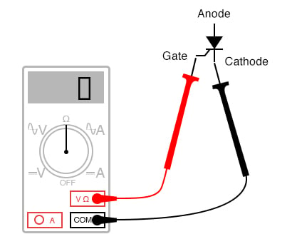
All other continuity measurements performed on an SCR will show ‘open’ (displayed as ‘OL’ on some digital multimeters). It’s important to understand that this test is very basic and does not provide a comprehensive assessment of the SCR. An SCR may give good ohmmeter readings but still be defective. Ultimately, the only reliable way to test an SCR is to apply a load current.
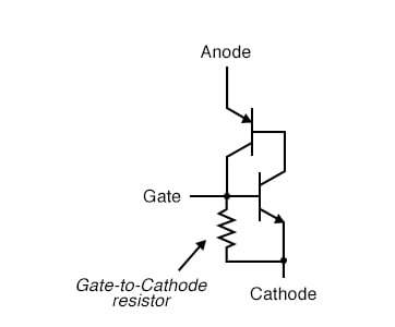
If you’re using a multimeter with a ‘diode check’ function, the gate-to-cathode junction voltage may or may not match the expected value for a silicon PN junction (around 0.7 volts). In some cases, you might read a much lower junction voltage, perhaps just hundredths of a volt. This is due to an internal resistor between the gate and cathode in some SCRs, which helps prevent false triggering by voltage spikes, circuit ‘noise,’ or static discharge. Essentially, this resistor ensures that a stronger triggering signal (higher current) is needed to latch the SCR. This feature is often found in larger SCRs, not in smaller ones. Keep in mind that an SCR with an internal resistor across the gate-cathode junction will show continuity in both directions between these two terminals, as shown in the figure below.
Basic Structure and Working Principle of SCR
SCR is a semiconductor device made up of four layers alternating between P-type and N-type materials, forming a PNPN structure. It has three terminals: Anode (A), Cathode (K), and Gate (G). Under an external voltage, the SCR remains in an off-state, and only turns on when an appropriate trigger signal is applied to the gate.
1.SCR Turn-On Conditions
Positive anode-cathode voltage: The anode voltage must be higher than the cathode voltage for the SCR to conduct.
Gate trigger signal: A small current is applied to the gate, triggering the device. This current causes the middle PN junction to break down, allowing current to flow through the device.
2. SCR Turn-Off
Once the SCR is on, it remains in a conducting state even if the gate signal is removed, until the current between the anode and cathode falls below the holding current. When the current drops below this level, the SCR turns off.
3. SCR Characteristics
Unidirectional conduction: The SCR only conducts when the anode is positively biased relative to the cathode and remains off under reverse voltage.
Controllability: The conduction of the SCR can be precisely controlled by adjusting the gate trigger signal.
Latch-on behavior: Once the SCR is turned on, it remains on until the anode-cathode current falls below the holding current, even if the gate signal is removed.
Types and Models of SCR
1.Based on Polarity
Undirectional SCR: Conducts only when the anode is positively biased, typically used in rectifier circuits.
Bidirectional SCR (Triac): Conducts in both directions and is commonly used in AC circuits for switching and regulation.
2.Based on Trigger Method
Current-triggered SCR: Triggered by a gate current and used in conventional switching applications.
Light-triggered SCR (LASCR): Activated by optical signals, suitable for high-isolation applications such as remote control in power systems.
3.Common SCR Models
2N5064: A small power SCR suitable for low-power AC or DC circuits.
TYN612: A medium-power SCR used in motor control and power management.
BT151: A high-power SCR widely applied in welding machines, dimmers, and other high-current control applications.
Application Fields of SCR
1.Rectification and Inversion
SCRs play a key role in rectifier and inverter circuits, converting AC to DC while allowing for controlled rectification to adjust output voltage. For example, in industrial motor control, SCRs manage the motor’s start and stop functions to prevent damaging current surges.
2.Dimming and Speed Control
In lighting dimming systems, SCRs control current flow to adjust brightness. By varying the firing angle, the conduction time of AC current is controlled, regulating the intensity of the light. The same principle is used in motor speed control by adjusting voltage.
3.Power System Control and Protection
SCRs are used in high-voltage power systems for switching equipment and grid protection. Their fast response makes them ideal for high-voltage DC (HVDC) systems, controlling power flow and improving system stability.
4.Heating and Temperature Control Systems
SCRs regulate heating elements by controlling the current in electric heating systems. For example, in household electric stoves or industrial furnaces, SCRs control the on-off cycle of current to precisely regulate heating power, improving efficiency.
Advantages and Limitations of SCR
Advantages
Efficient power control: SCRs handle high current and voltage, making them suitable for high-power control applications.
Simple structure, low cost: Compared to other complex power electronic devices, SCRs are relatively simple in structure and inexpensive to manufacture.
High reliability: SCRs are known for their high reliability and long service life, even in harsh environments.
Limitations
Cannot switch off DC circuits: Once turned on in a DC circuit, SCRs cannot be turned off via gate control, which limits their use in certain applications.
Complex triggering control: In high-frequency switching scenarios, precise control of the trigger signal is required to avoid false triggering or non-conduction.
Future Development of SCR
1.Smart Control
Future SCRs may integrate with digital signal processors (DSP) and microcontrollers (MCU) to form smarter control systems. This integration will enable more precise control of switching times and allow SCRs to dynamically adjust based on load conditions, improving system efficiency and reliability.
2.New Materials and Processes
Advancements in semiconductor materials, such as silicon carbide (SiC) and gallium nitride (GaN), are increasingly being applied to high-power devices. Compared to traditional silicon-based materials, these new materials offer better performance and higher efficiency in high-frequency and high-temperature environments. Future SCRs based on these materials will have higher power density, lower loss, and wider application scenarios.
3.Energy Management and Renewable Energy
SCRs will continue to play a key role in renewable energy systems like solar and wind power generation. By optimizing power conversion devices, SCRs can enhance the efficiency of renewable energy usage and enable precise control within smart grids.
As a vital power electronic device, SCRs offer efficient power control, simple structure, and a wide range of applications in modern industrial and consumer power control systems. As technology progresses, SCR performance will continue to improve, and their application fields will further expand. Whether in traditional power systems or in new energy and smart control fields, SCRs will remain indispensable for future developments.
For more information please contact us:emi-ic.com